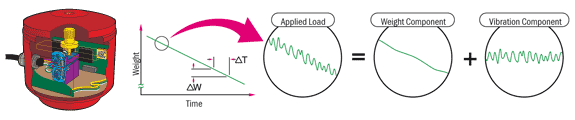
Coperion K-Tron (USA) - Consider a loss-in-weight feeder operating in a typical plant environment. Feed rate control is achieved by continuously weighing the entire feeding system, then controlling the rate at which the system loses weight. In the above plot of feeder system weight vs time, the desired feed rate is represented as the change in system weight per unit time, or simply the negative slope of the weight signal. The total load applied to the weighing system is a composite of the actual system weight plus the variable force contributed by in-plant vibration.
Load Measurement:
The total applied load (A) causes wire (B) to change its resonant frequency (10-15 KHz measurement range). The signal (C) is converted to a square wave (D).
Impulse Counting:
Impulse counting begins at the left edge of a square wave and continues until the first left edge of the next sample group is detected. During each measurement period, counts of wire vibration are recorded in one register while clock pulses are simultaneously counted in separate registers. To obtain all data without loss, the detection of the end of a sample group triggers the entry of the impulse count total and elapsed time into a set of capture registers and a new sample group begins.
Frequency Calculation:
While counting continues uninterrupted in the primary registers, an on-board microcomputer then determines the frequency for each sample group to high computational resolution using 32-bit floating point calculations.
Temperature Compensation:

Temperature dependence of the load/ frequency relationship is minimized by careful choice of the materials from which the wire and other sensor elements are manufactured. The small residual temperature effect is mathematically compensated via application of zero and span coefficients determined during manufacture, and stored in the SFT’s EEPROM. A highly responsive temperature sensor is thermally coupled to the wire system. Output frequency is between 18 and 30 kHz. Temperature measurement is highly linear and resolution is better than 0.001°C.
Linearization:

The relationship between the applied load and the wire’s frequency is very nearly parabolic where wire frequency is proportional to the square root of the applied load. Polynomial coefficients for the linearization are determined for each SFT during manufacture, and are stored in the SFT’s EEPROM. Coefficients retain their validity throughout the sensor’s life, eliminating the need for periodic recalibration.
Digital Filtering:
The continuous stream of weight samples is then digitally filtered. The digital filter can be adjusted for different cut off frequencies (0.1 - 10 Hz) depending on the individual feeder configuration.


How Coperion K-Tron SFT Technology Delivers High-Precision Weighing Even in Difficult Plant Environments
- By Coperion
- Posted on Jun 18, 2015
For more information about this article from Coperion click here.
© Coperion / International Weighing Review


Popular News


Interested? Submit your enquiry using the form below:
Only available for registered users. Sign In to your account or register here.