

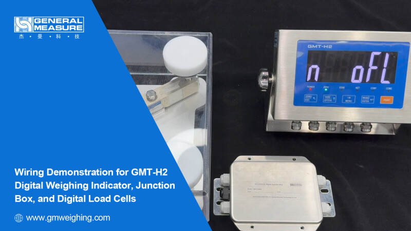
General Measure Technology Co. Ltd. (China) - Press Release: Digital Weighing Indicator GMT-H2 Wire Connection with Digital Junction Box and Load Cells
Hello everyone! Welcome to General Measure's channel. In this episode, we'll demonstrate how to wire the digital weighing indicator GMT-H2 with the digital junction box and digital load cells.
1. Connection Between the Indicator and the Junction Box
First, let's connect the indicator to the junction box. Connect the wires in the following order: A, B, SHDL, V+, and V−.
(Tip: Junction box wire color codes: A (green), B (white), SHDL/shield (purple), V+ (red), V− (black))
Next, connect the wires to the indicator in the same sequence: A, B, SHDL, 12V+, and GND.
(Tip: Indicator wire color codes: A (green), B (white), SHDL/shield (purple), 12V+ (red), GND (black))
After wiring, double-check the wiring sequence. Incorrect wiring may damage the load cell module.
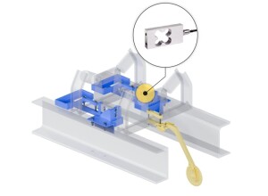
2. Connection Between the Digital Load Cells and the Junction Box
Then let's connect the digital load cells to the junction box. In this case, four load cells need to be connected to the junction box integrated with digital and analog signal.
Follow the wiring sequence: V+, V−, A, B, SHDL.
Refer to the manual for the exact wire sequence and connect the wires to the corresponding terminals of the junction box.
Once the first load cell is wired, connect the remaining three in the same order to the terminals of the junction box.
After all connections are complete, verify the wiring sequence to avoid damage to the load cell module. Finally, turn on the switches of the digital load cell terminals inside the junction box.
(Load cell wire color codes: V+ (red), V− (black), A (green), B (white), SHDL/shield (purple))
3. Parameter Settings
After wiring, it's necessary to configure the indicator parameters.
Step 1: Powering the Indicator
Use a 24V DC power supply to power on the GMT-H2. Power connection: 24−, 24+
Step 2: Set the Number of Load Cells
After powering on, press the MENU key, then press it again to switch into the "Digi" menu. Press ENTER and input the default password: six zeros (000000).
Enter the d1 menu and press ENTER to confirm.
Press the TARE/OPTION key to set the number of connected load cells to 4 (the actual number connected).
Step 3: Load Cells Search
While in the "Digi" menu, press MENU to switch to the d2. The screen will display “num 0”.
Press the TARE/OPTION key to begin searching for load cells. The display will show “Ad on”.
Wait for the search to complete. The screen will then update with the actual number of connected modules. At this point, the indicator is ready for use (The display shows 4 load cell connected).
That concludes the wiring and configuration guide for the GMT-H2 digital weighing indicator, junction box, and digital load cells.
Watch the video.
Thanks for watching, and see you next time!


Interested? Submit your enquiry using the form below:
Only available for registered users. Sign In to your account or register here.