
Corner Trimming Compensation – Optimization and Limits of the Digital Junction Box
Introduction: The Necessity of Corner Adjustment
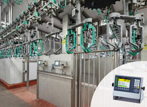
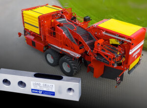
In platform scales, floor scales, and weighbridges that utilize four or more load cells, the principle of corner loading dictates that the scale must display the same weight value regardless of where the load is placed on the platform. Manufacturing tolerances in load cells, inevitable variations in mechanical mounting, and slight differences in cable resistance often cause deviations in readings across the four corners. Corner Trimming is the calibration procedure designed to compensate for these variances. Traditionally, this was done manually using potentiometers in an analog junction box; modern systems achieve this digitally using an advanced Digital Junction Box (DJB) or intelligent weighing terminal.
Analog vs. Digital Trimming
The method of compensation critically impacts the stability and accuracy of the final scale system:
Analog Corner Trimming (Traditional Method)
- Mechanism: Small resistors (potentiometers) are inserted into the signal circuit of each load cell line inside a junction box. The resistors are manually adjusted to attenuate the signal from the "hotter" (higher reading) corners, balancing the output voltages.
- Limitation: This method reduces the overall output sensitivity (mV/V) of the system, potentially lowering the resolution and, crucially, is susceptible to temperature drift and vibration.
Digital Corner Trimming (Modern Method)
- Mechanism: Each load cell is connected to an individual high-speed Analog-to-Digital Converter (ADC) input inside the Digital Junction Box or summing device. The system measures the raw output of each cell independently. Compensation is applied through software, mathematically scaling the contribution of each cell to the total weight calculation.
- Advantage: Digital trimming does not introduce resistors into the circuit, preserving the full signal strength and resolution (mV/V) of the system. Compensation values are stable and automatically applied upon power-up.
The Optimization Process (Digital Trimming)
Digital trimming allows for a precise, non-destructive compensation routine:
Procedure
- Zeroing: The system establishes the zero point for all four load cells collectively.
- Reference Load: A known test weight is placed sequentially over each load cell mounting point (or corner).
- Calculation: The terminal calculates a trim factor (scaling multiplier) for each cell based on the deviation of its corner reading from the average corner reading. The cell with the lowest reading usually receives a factor of 1.000, and others receive factors less than 1.000.
- Application: The software multiplies the current reading of each cell by its respective trim factor before summing the results for the final display.
This process ensures that the scale's response is uniform across the entire platform without sacrificing the quality of the raw signal.
Limits and Advanced Diagnostics
While digital trimming is superior, it cannot correct for fundamental mechanical or electrical flaws.
Limits of Compensation
- Excessive Deviation: If the raw output difference between the highest and lowest reading cell exceeds a certain limit (e.g., 2% to 5%), compensation may be technically possible but legally disallowed (OIML/NTEP) or result in poor long-term stability. Excessive deviation indicates a mechanical fault (e.g., binding, uneven mounting, or incorrect load cell capacity selection).
- Temperature Effects: The system must assume the temperature effects (creep and span drift) are identical across all four cells. If one cell's temperature compensation is faulty or if it is thermally isolated differently, digital trimming will introduce errors as the ambient temperature changes.
Advanced DJB Diagnostics
Modern DJBs are essential diagnostic tools because they allow technicians to remotely monitor the individual output of all four cells in real-time. This capability enables predictive maintenance by immediately alerting the user if one cell begins to drift significantly (a sign of moisture ingress or seal failure), long before the overall corner-trimmed weight reading becomes obviously inaccurate.
Digital corner trimming is the industry standard for high-accuracy multi-cell systems, providing necessary corrective software without the inherent signal degradation and long-term instability associated with analog methods.