Load Cell Diagnostics: 5 Common Failure Modes and Rapid Troubleshooting Techniques
The Importance of the Load Cell in Weighing Reliability
The load cell is the most critical and sensitive component of any electronic weighing system, from industrial weighbridges to high-precision bench scales. It is an electro-mechanical device that converts force (weight) into a measurable electrical signal. When a scale delivers inconsistent or zero readings, the load cell is often the primary culprit.
Understanding the five most common failure modes and knowing how to perform rapid diagnostics is essential for minimizing downtime and avoiding costly unnecessary replacements. This guide is designed for maintenance technicians and facility managers to quickly isolate the problem.
1. Failure Mode: Electrical Overload / Lightning Damage
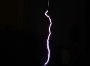
Electrical overload is typically caused by power surges, faulty wiring, or—most commonly—lightning strikes, which can induce current into the load cell wiring.
Diagnostic Symptoms:
- Scale Reads Zero or Max Capacity: The indicator often shows an extreme or non-responsive reading.
- Physical Damage: Burn marks or melting visible on the cable entry point or within the junction box.
Rapid Troubleshooting Technique: Resistance Test
Use a multimeter to measure resistance across the input (excitation) and output (signal) wires of the load cell (or at the junction box):
- Excitation Resistance: Measure resistance between the (+) Excitation and (-) Excitation wires. The reading should closely match the manufacturer's specification (typically 350Ω or 700Ω).
- Signal Resistance: Measure resistance between the (+) Signal and (-) Signal wires. This reading should also match the specification.
- Result: A reading that is significantly higher or open-circuit (infinite) indicates a burned-out internal strain gauge or damaged wiring due to high voltage.
2. Failure Mode: Water Ingress or Moisture Contamination
This is common in washdown (IP-rated) scales where the seal or cable gland has degraded, allowing humidity or liquid to penetrate the internal strain gauge.
Diagnostic Symptoms:
- Unstable/Drifting Readings: The displayed weight constantly fluctuates, especially after a cleaning cycle or heavy rain.
- Intermittent Errors: The scale works fine in dry conditions but fails in humid or cold environments (due to condensation).
Rapid Troubleshooting Technique: Insulation Resistance Test (Bridge to Ground)
This test checks for electrical leakage between the load cell's internal wiring and its metallic body (ground).
- Connect Multimeter: Set the multimeter to measure high resistance (MΩ, Megaohms).
- Measure: Place one probe on the metal body of the load cell (ground) and the other probe sequentially on each of the four wires (Excitation and Signal).
- Result: Any reading significantly below 5,000 MΩ (or the manufacturer's spec) indicates moisture has compromised the insulation. The load cell must be replaced.
3. Failure Mode: Mechanical Damage (Non-Linearity)
Caused by physical trauma, such as a forklift impacting a platform scale, or severe overload that has permanently deformed the load cell body.
Diagnostic Symptoms:
- Non-Linearity: The scale is accurate at zero and full capacity but wildly inaccurate at mid-range loads.
- Poor Return to Zero: After removing a heavy load, the scale does not return to zero, showing a permanent offset.
Rapid Troubleshooting Technique: Corner/Eccentric Load Test
This simple test isolates the mechanical integrity of individual load cells.
- Apply Test Weight: Place a known test weight (typically 1/4 of the scale capacity) in the center of the platform and record the reading.
- Move Weight: Move the exact same test weight sequentially to each corner (directly over the load cell) and record the readings.
- Result: If any corner reading deviates by more than the accepted tolerance (often set by the indicator), the load cell beneath that corner is mechanically damaged or installed incorrectly (e.g., binding).
4. Failure Mode: Zero Drift (Thermal or Stress)
Zero drift refers to the scale's zero point gradually shifting over time, often due to temperature changes or continuous static load (creep).
Diagnostic Symptoms:
- Zero Shift: The scale shows a weight value (e.g., 50 kg) when the platform is empty.
- Temperature Dependency: The zero reading changes significantly between morning (cold) and afternoon (warm).
Rapid Troubleshooting Technique: Stability Check and Wait Time
This issue is less about immediate failure and more about system stability.
- Isolate Power: Turn off the scale and let it rest for a defined period (e.g., 30 minutes).
- Power On and Monitor: Turn the scale back on without load. The zero reading should stabilize quickly.
- Result: If the zero value continues to drift by more than 1–2 display divisions every minute, the load cell's internal compensation resistors may be failing, or the wrong load cell for the temperature range was installed.
5. Failure Mode: Wiring and Junction Box Faults
Often, the load cell itself is fine, but the connections leading to it are compromised by vibration, loose terminals, or corrosion inside the junction box.
Diagnostic Symptoms:
- Intermittent Connectivity: The scale randomly cuts out or displays an error code (e.g., "OL" for Overload).
- Impact Sensitivity: Tapping the junction box or cable causes the display to change rapidly.
Rapid Troubleshooting Technique: Voltage Output Test and Visual Check
This is the simplest test and should always be done first.
- Visual Inspection: Open the junction box. Look for corrosion on terminals, loose screws, or frayed wires. Re-torque or clean connections.
- Voltage Test: Measure the voltage output (mV) between the (+) Signal and (-) Signal wires at the junction box (under load). Compare the voltage from each load cell connected to the indicator.
- Result: Significant voltage variation between cells (more than 1-2mV) on the same scale indicates a faulty cell or, more likely, a bad trim pot or loose wiring inside the junction box, requiring recalibration and repair.
Conclusion: Prevention and Calibration
In many cases, the perceived "load cell failure" is actually a fault in the junction box or a mechanical binding issue. A technician who understands these five failure modes can save hours of diagnostic time and the cost of an expensive, unnecessary load cell replacement.
Routine visual inspections, scheduled calibration, and immediate attention to subtle reading drifts are the best practices for maximizing the lifespan and accuracy of your weighing assets.


